
Semaphore Translator
Vanderbilt University · Spring 2023
Aaron Gothard, Saksham Sharma, Julia Quilici
What is a Semaphore?
Flag Semaphore codes originated in 1866, as a method of communication between ships to replace shutter semaphores that were placed on lighthouses Flag semaphores utilize two square flags that a person can hold in one of 7 positions. These positions step through ¾ of a circle in steps of 45 degrees.
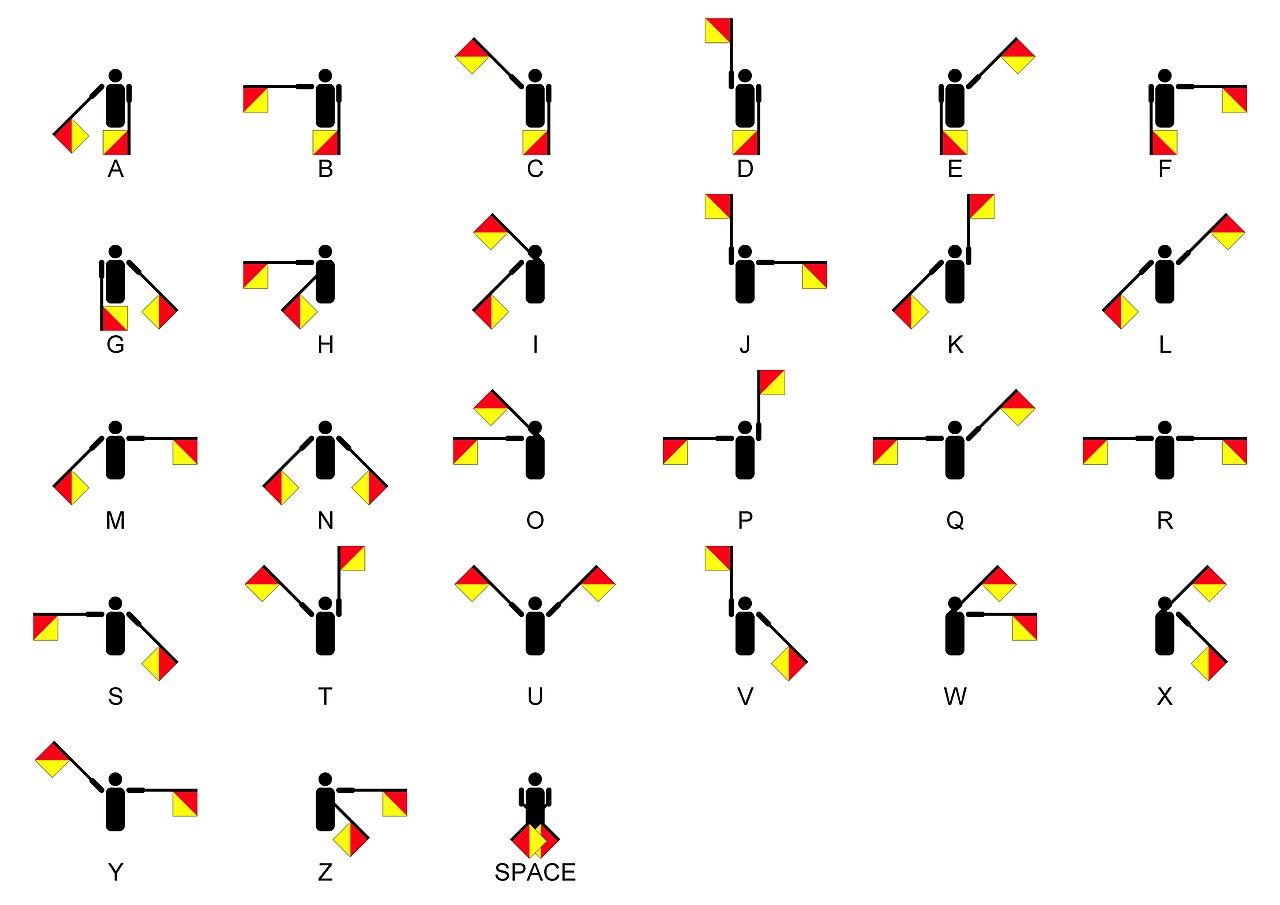
By numbering each arm position 1-7 and separating flags by their independent positions, 2-digit indices can be created that will identify any position.
Hardware
- Data Acquisition (DAQ) Board
- Accelerometers
- Custom accellerometer wrist mounts
- 3v Power Supply
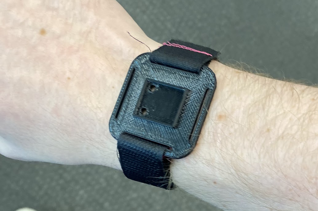 The wrist mount for our accelerometers. Designed, 3D-printed and sewn by yours truly
Code Overview
The structure of our code followes one large flat sequence. This ensures that our logic runs sequentially. I’ll go over each frame below:
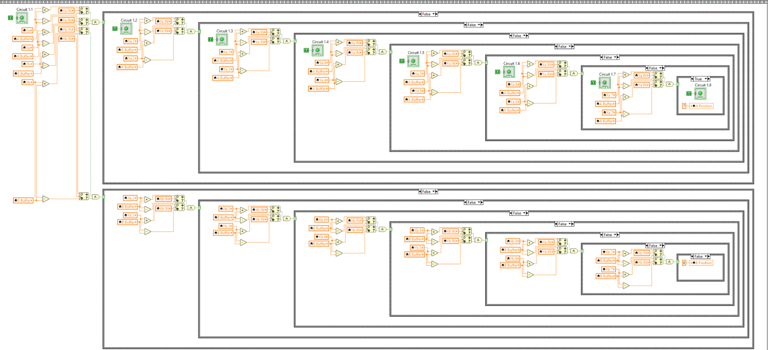
Frame 1
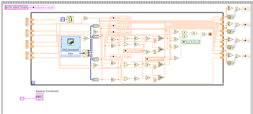
Since this is a weekly lab, we rarely use the same hardware twice in a row. To combat the differences in accelerometers and DAQ boards, this first frame runs through a quick calibration sequence. It takes the input from the accelerometers and saves the x and y positions of both as Xai, Yai, Xbi, Ybi in order to calibrate the accelerometers (i is position number). This frame is repeated 7 times for 7 different positions.
Frame 2
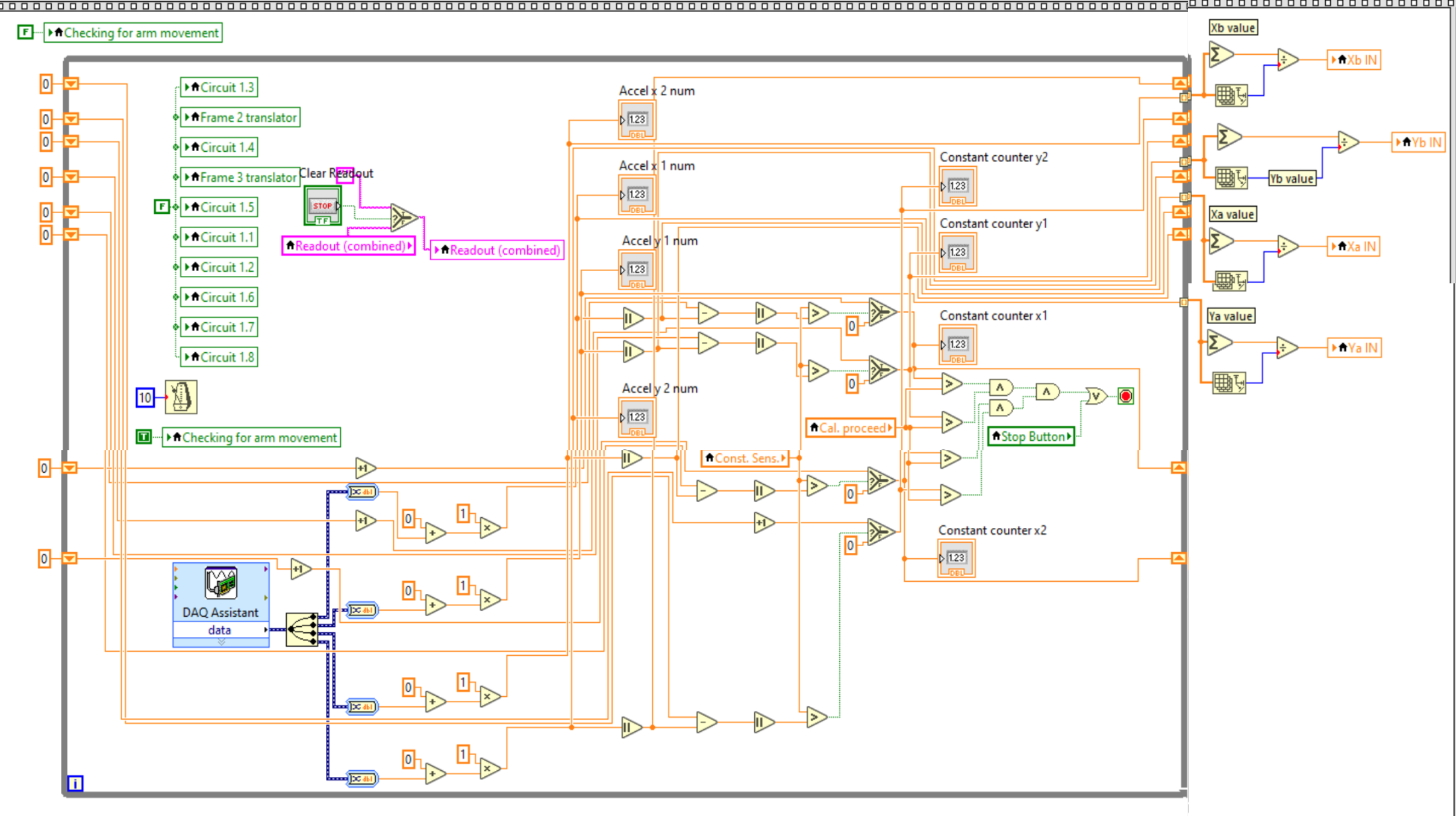
This is the main loop of the code. Here it reads the values from the accelerometers and checks if they are holding still for long enough to continue. Waiting until the arms are still is crucial to ensure as few mistakes as possible.
Frame 3
This portion of the code uses the steady accelerometer readings from the last frame and compares against the calibration data from each position in order to determine the positions (1-7) that each hand is in. Though it looks messy, the use of many nested case structures was necessary to prevent LabVIEW from becoming too slow.
Frame 4
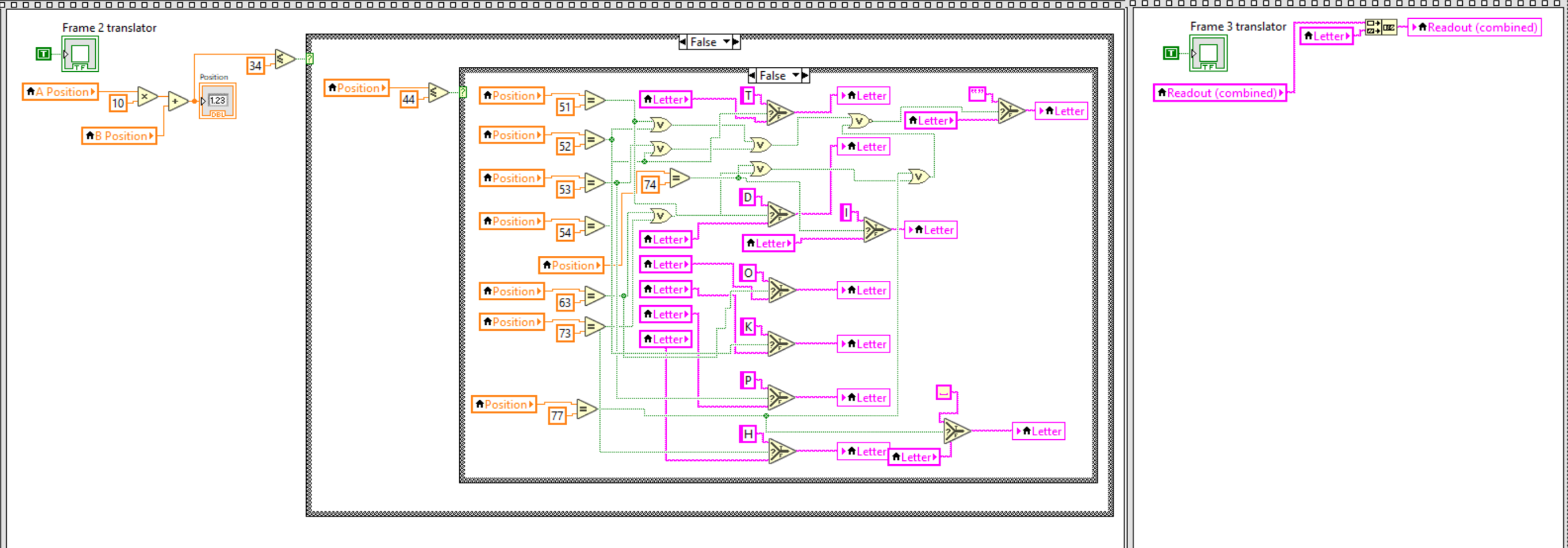
This frame takes the two positions from the last frame and checks against a dictionary of valid semaphore positions to decide whether they correspond to a valid letter and what letter that is. This letter is then appended to the end of the string being displayed on the front panel.
Calibration Analysis
- Takes approximately 1 minute to finish calibration for all 7 positions
- Initial testing(not calibrated): 13.04% correctness with letter translation
- Improved testing(with calibration): 75% correctness with letter translation and word formation
- String of letters that was supposed to read HELLOWORLD instead read HCELLO WORLDO
- Most errors attributed to human arm positioning error; code was translating correctly, if not accurately to our desires
Issues we faced:
- Accelerometers wouldn’t cooperate in regards to calibration
- Ensuring the accelerometers were always planar was a challenge as even with a slight movement in the z direction it would interfere with the calibration data and therefore not produce letters during the actual translation
Changes we would make if we had more time:
- Make the mount and entire set up more portable or easy to manage
- Spend more time on clearing the clutter of the code (it’s overwhelming to look at)
- Add a ‘send’ button to ensure no position was taken accidentally
Conclusion
Though there is a lot that we would like to improve upon, this project was a considerable jump in complexity compared other assignments in this lab. We got above a 100% on this final project and exceeded every expectation set upon us. We made custom wrist mounts with velcro straps, we had multi stage logic, and we succeeded in the goal we set out upon. This was truly an experience that I can be proud of, and looking back this was one of my more well-rounded projects in the early college years.